Vivid 300-135 Dumps Questions 2021
Want to know ccnp tshoot 300 135 dumps pdf features? Want to lear more about ccnp tshoot 300 135 dumps pdf experience? Study ccnp tshoot 300 135. Gat a success with an absolute guarantee to pass Cisco 300-135 (Troubleshooting and Maintaining Cisco IP Networks (TSHOOT)) test on your first attempt.
Free demo questions for Cisco 300-135 Exam Dumps Below:
NEW QUESTION 1
The following command is issued on a Cisco Router: Router(configuration)#logging console warnings Which alerts will be seen on the console?
- A. Warnings only
- B. debugging, informational, notifications, warnings
- C. warnings, errors, critical, alerts, emergencies
- D. notifications, warnings, errors
- E. warnings, errors, critical, alerts
Answer: C
Explanation: Cisco routers prioritize log messages into 8 levels (0-7), as shown below: LevelLevel NameDescription
0 Emergencies System is unusable 1 Alerts Immediate action needed 2 Critical Critical conditions
3 Errors Error conditions
4 Warnings Warning conditions
5 Notifications Informational messages
6 Informational Normal but significant conditions 7 Debugging Debugging messages
When you enable logging for a specific level, all logs of that severity and greater (numerically less) will be logged. In this case, when you enable console logging of warning messages (level 4), it will log levels 0-4, making the correct answer warnings, errors, critical, alerts, and emergencies.
NEW QUESTION 2
Scenario:
A customer network engineer has edited their OSPF network configuration and now your customer is experiencing network issues. They have contacted you to resolve the issues and return the network to full functionality.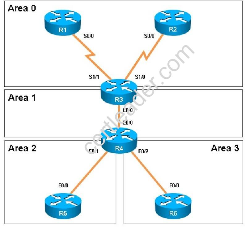


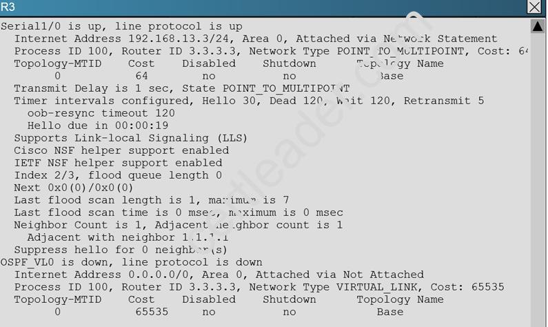
The OSPF neighbour relationship has been lost between R1 and R3. What is causing this problem?
- A. The serial interface in R1 should be taken out of the shutdown state.
- B. A neighbor statement needs to be configured in R1 and R3 pointing at each other.
- C. The R1 network type should be changed to point-to-multipoint non-broadcast.
- D. The hello, dead and wait timers on R1 need to be reconfigured to match the values on R3.
Answer: C
Explanation: In order for two OSPF routers to become neighbors, they must have matching network types across the links. In this case, we see that R1 has been configured as non-broadcast and R3 is using point to point non-broadcast.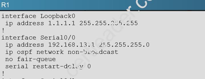
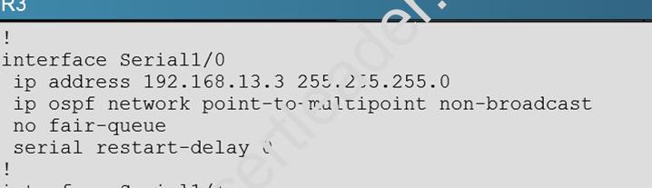
This can be seen by issuing the “show running-config” command on each router, or the “show ip ospf interface” command:
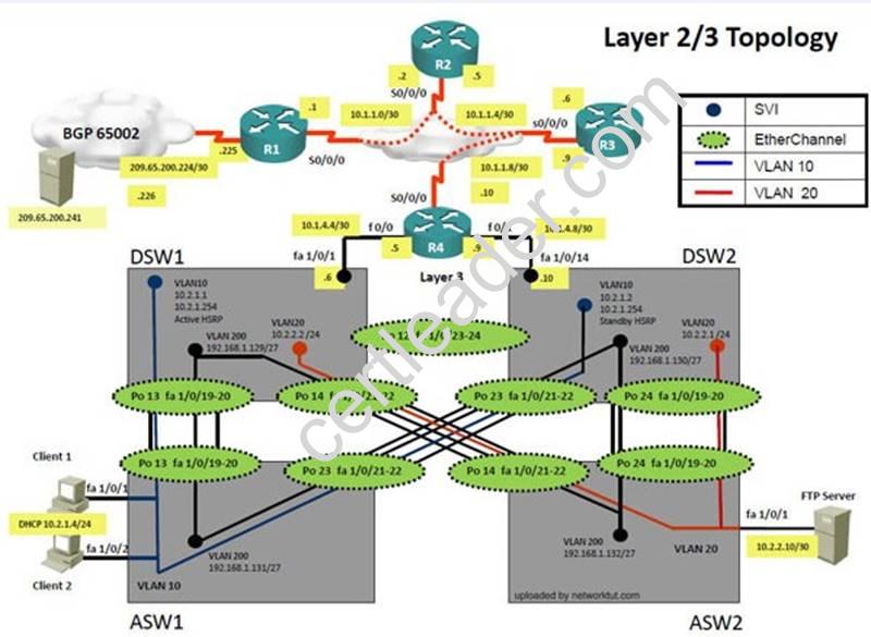
Topic 6, Ticket 1: Switch Port Trunk
Topology Overview (Actual Troubleshooting lab design is for below network design)
Client Should have IP 10.2.1.3
EIGRP 100 is running between switch DSW1 & DSW2
OSPF (Process ID 1) is running between R1, R2, R3, R4
Network of OSPF is redistributed in EIGRP
BGP 65001 is configured on R1 with Webserver cloud AS 65002
HSRP is running between DSW1 & DSW2 Switches
The company has created the test bed shown in the layer 2 and layer 3 topology exhibits.
This network consists of four routers, two layer 3 switches and two layer 2 switches.
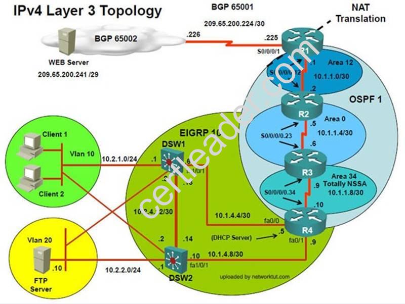
In the IPv4 layer 3 topology, R1, R2, R3, and R4 are running OSPF with an OSPF process number 1. DSW1, DSW2 and R4 are running EIGRP with an AS of 10. Redistribution is enabled where necessary.
R1 is running a BGP AS with a number of 65001. This AS has an eBGP connection to AS 65002 in the ISP’s network. Because the company’s address space is in the private range.
R1 is also providing NAT translations between the inside (10.1.0.0/16 & 10.2.0.0/16) networks and outside (209.65.0.0/24) network.
ASW1 and ASW2 are layer 2 switches.
NTP is enabled on all devices with 209.65.200.226 serving as the master clock source.
The client workstations receive their IP address and default gateway via R4’s DHCP server.
The default gateway address of 10.2.1.254 is the IP address of HSRP group 10 which is running on DSW1 and DSW2.
In the IPv6 layer 3 topology R1, R2, and R3 are running OSPFv3 with an OSPF process number 6. DSW1, DSW2 and R4 are running RIPng process name RIP_ZONE.
The two IPv6 routing domains, OSPF 6 and RIPng are connected via GRE tunnel running over the underlying IPv4 OSPF domain. Redistrution is enabled where necessary.
Recently the implementation group has been using the test bed to do a ‘proof-of-concept’ on several
implementations. This involved changing the configuration on one or more of the devices. You will be presented with a series of trouble tickets related to issues introduced during these configurations.
Note: Although trouble tickets have many similar fault indications, each ticket has its own issue and solution.
Each ticket has 3 sub questions that need to be answered & topology remains same. Question-1 Fault is found on which device,
Question-2 Fault condition is related to,
Question-3 What exact problem is seen & what needs to be done for solution
Client is unable to ping IP 209.65.200.241
Solution
Steps need to follow as below:-
When we check on client 1 & Client 2 desktop we are not receiving DHCP address from R4 Ipconfig ----- Client will be getting 169.X.X.X
On ASW1 port Fa1/0/ 1 & Fa1/0/2 access port VLAN 10 was assigned which is using IP address 10.2.1.0/24
Sh run ------- & check for running config of int fa1/0/1 & fa1/0/2
====================================================
interface FastEthernet1/0/1switchport mode accessswitchport access vlan 10interface FastEthernet1/0/2switchport mode accessswitchport access vlan 10
====================================================
We need to check on ASW 1 trunk port the trunk Po13 & Po23 were receiving VLAN 20 & 200 but not VLAN 10 so that switch could not get DHCP IP address and was failing to reach IP address of Internet
Change required: On ASW1 below change is required for switch-to-switch connectivity..
int range portchannel13,portchannel23 switchport trunk allowed vlan none switchport trunk allowed vlan 10,200
NEW QUESTION 3
Refer to the exhibit.
How would you confirm on R1 that load balancing is actually occurring on the default-network (0.0.0.0)?
- A. Use ping and the show ip route command to confirm the timers for each default network resets to 0.
- B. Load balancing does not occur over default networks; the second route will only be used for failover.
- C. Use an extended ping along with repeated show ip route commands to confirm the gateway of last resort address toggles back and forth.
- D. Use the traceroute command to an address that is not explicitly in the routing table.
Answer: D
NEW QUESTION 4
Refer to the exhibit.
Which IP address should be configured as the tunnel source on the HQ router for maximum resiliency?
- A. 10.20.1.1.0
- B. 10.30.1.1
- C. 172.18.10.2
- D. 192.168.10.1
Answer: D
NEW QUESTION 5
The implementation group has been using the test bed to do an IPv6 'proof-of-concept1. After several changes to the network addressing and routing schemes, a trouble ticket has been opened indicating that the loopback address on R1 (2026::111:1) is not able to ping the loopback address on DSW2 (2026::102:1).
Use the supported commands to isolate the cause of this fault and answer the following question. What is the solution to the fault condition?
- A. Under the interface SerialO/0/0.23 configuration enter the ipv6 ospf 6 area 0 command.
- B. Under the interface SerialO/0/0.12 configuration enter the ipv6 ospf 6 area 12 command.
- C. Under ipv6 router ospf 6 configuration enter the network 2026::1:/122 area 0 command.
- D. Under ipv6 router ospf 6 configuration enter the no passive-interface default command
Answer: A
Explanation: As explained in question one of this ticket, we can then see that OSPFv3 has not been enabled on the interface to R3:
Screen Shot 2015-03-11 at 10
So the problem is with R2, related to IPV6 Routing, and the fix is to enable the “ipv6 ospf 6 area 0”command under the serial 0/0/0.23 interface. We need to enable this interface for area 0 according to the topology diagram.
Topic 20, Ticket 15: IPv6 Routing Issue 2
Topology Overview (Actual Troubleshooting lab design is for below network design)
Client Should have IP 10.2.1.3
EIGRP 100 is running between switch DSW1 & DSW2
OSPF (Process ID 1) is running between R1, R2, R3, R4
Network of OSPF is redistributed in EIGRP
BGP 65001 is configured on R1 with Webserver cloud AS 65002
HSRP is running between DSW1 & DSW2 Switches
The company has created the test bed shown in the layer 2 and layer 3 topology exhibits. This network consists of four routers, two layer 3 switches and two layer 2 switches.
In the IPv4 layer 3 topology, R1, R2, R3, and R4 are running OSPF with an OSPF process number 1. DSW1, DSW2 and R4 are running EIGRP with an AS of 10. Redistribution is enabled where necessary.
R1 is running a BGP AS with a number of 65001. This AS has an eBGP connection to AS 65002 in the ISP’s network. Because the company’s address space is in the private range.
R1 is also providing NAT translations between the inside (10.1.0.0/16 & 10.2.0.0/16) networks and outside (209.65.0.0/24) network.
ASW1 and ASW2 are layer 2 switches.
NTP is enabled on all devices with 209.65.200.226 serving as the master clock source.
The client workstations receive their IP address and default gateway via R4’s DHCP server.
The default gateway address of 10.2.1.254 is the IP address of HSRP group 10 which is running on DSW1 and DSW2.
In the IPv6 layer 3 topology R1, R2, and R3 are running OSPFv3 with an OSPF process number 6. DSW1, DSW2 and R4 are running RIPng process name RIP_ZONE.
The two IPv6 routing domains, OSPF 6 and RIPng are connected via GRE tunnel running over the underlying IPv4 OSPF domain. Redistrution is enabled where necessary.
Recently the implementation group has been using the test bed to do a ‘proof-of-concept’ on several implementations. This involved changing the configuration on one or more of the devices. You will be
presented with a series of trouble tickets related to issues introduced during these configurations.
Note: Although trouble tickets have many similar fault indications, each ticket has its own issue and solution.
Each ticket has 3 sub questions that need to be answered & topology remains same. Question-1 Fault is found on which device,
Question-2 Fault condition is related to,
Question-3 What exact problem is seen & what needs to be done for solution
===============================================================================


NEW QUESTION 6
Which of the following is an accurate description of the command copy startup-config
ftp://kevin:cisco@192.168.1.74?
- A. The configuration on the FTP server is copied to RAM.
- B. The command is not valid on a Cisco router.
- C. The configuration file in RAM is copied to an FTP server.
- D. The configuration file in NVRAM is copied to an FTP server.
- E. The configuration on the FTP server is copied to NVRAM.
- F. The configuration will be copied from NVRAM to an FTP server with a filename of Kevin.
Answer: D
NEW QUESTION 7
You must connect two remote sites over the public internet. Multicast support, security, and simplicity are required. Which tunneling technology sould you consider?
- A. MPLS
- B. GRE over IPsec
- C. GET VPN
- D. IPsec
Answer: B
NEW QUESTION 8
The implementations group has been using the test bed to do a ‘proof-of-concept’ that requires both Client 1 and Client 2 to access the WEB Server at 209.65.200.241. After several changes to the network addressing, routing scheme, DHCP services, NTP services, layer 2 connectivity, FHRP services, and device security, a trouble ticket has been opened indicating that Client 1 cannot ping the 209.65.200.241 address.
Use the supported commands to isolated the cause of this fault and answer the following questions. The fault condition is related to which technology?
- A. Under the global configuration mode enter no access-list 10 command.
- B. Under the global configuration mode enter no access-map vlan 10 command.
- C. Under the global configuration mode enter no vlan access-map test1 10 command.
- D. Under the global configuration mode enter no vlan filter test1 vlan-list 10 command.
Answer: C
Explanation: On DSW1, VALN ACL, Need to delete the VLAN access-map test1 whose action is to drop access-list 10; specifically 10.2.1.3
Topic 16, Ticket 11 : IPV6 OSPF
Topology Overview (Actual Troubleshooting lab design is for below network design)
Client Should have IP 10.2.1.3
EIGRP 100 is running between switch DSW1 & DSW2
OSPF (Process ID 1) is running between R1, R2, R3, R4
Network of OSPF is redistributed in EIGRP
BGP 65001 is configured on R1 with Webserver cloud AS 65002
HSRP is running between DSW1 & DSW2 Switches
The company has created the test bed shown in the layer 2 and layer 3 topology exhibits. This network consists of four routers, two layer 3 switches and two layer 2 switches.
In the IPv4 layer 3 topology, R1, R2, R3, and R4 are running OSPF with an OSPF process number 1. DSW1, DSW2 and R4 are running EIGRP with an AS of 10. Redistribution is enabled where necessary.
R1 is running a BGP AS with a number of 65001. This AS has an eBGP connection to AS 65002 in the ISP’s network. Because the company’s address space is in the private range.
R1 is also providing NAT translations between the inside (10.1.0.0/16 & 10.2.0.0/16) networks and outside (209.65.0.0/24) network.
ASW1 and ASW2 are layer 2 switches.
NTP is enabled on all devices with 209.65.200.226 serving as the master clock source.
The client workstations receive their IP address and default gateway via R4’s DHCP server.
The default gateway address of 10.2.1.254 is the IP address of HSRP group 10 which is running on DSW1 and DSW2.
In the IPv6 layer 3 topology R1, R2, and R3 are running OSPFv3 with an OSPF process number 6. DSW1, DSW2 and R4 are running RIPng process name RIP_ZONE.
The two IPv6 routing domains, OSPF 6 and RIPng are connected via GRE tunnel running over the underlying IPv4 OSPF domain. Redistrution is enabled where necessary.
Recently the implementation group has been using the test bed to do a ‘proof-of-concept’ on several
implementations. This involved changing the configuration on one or more of the devices. You will be presented with a series of trouble tickets related to issues introduced during these configurations.
Note: Although trouble tickets have many similar fault indications, each ticket has its own issue and solution.
Each ticket has 3 sub questions that need to be answered & topology remains same. Question-1 Fault is found on which device,
Question-2 Fault condition is related to,
Question-3 What exact problem is seen & what needs to be done for solution
===============================================================================

Solution
Steps need to follow as below:-
When we check on client 1 & Client 2 desktop we are not receiving DHCP address from R4 ipconfig ----- Client will be receiving IP address 10.2.1.3
From Client PC we can ping 10.2.1.254….
But IP 10.2.1.3 is able to ping from R4, R3, R2, R1.
Since the problem is R1 (2026::111:1) is not able to ping loopback of DSW1 (2026::102:1).
Kindly check for neighbourship of routers as IPV6…. As per design below neighbourship should be present for IPV6
R1 ---R2 --- R3 --- R4--- DSW1 & DSW2 ----- Neighbourship between devices of IPV6
R2 IPV6 OSPF neighbourship is with R1
R3 IPV6 OSPF neighbourship is with R4

As per above snapshot we cannot see IPV6 neighbourship between R2 & R3 when checked interface configuration ipv6 ospf area 0 is missing on R2 which is connected to R3
Change required: On R2, IPV6 OSPF routing, Configuration is required to add ipv6 ospf 6 area 0 under interface serial 0/0/0.23
------------------------------------------------------------------------------------------------------------------------------
NEW QUESTION 9
The implementations group has been using the test bed to do a ‘proof-of-concept’ that requires both Client 1 and Client 2 to access the WEB Server at 209.65.200.241. After several changes to the network addressing, routing scheme, DHCP services, NTP services, layer 2 connectivity, FHRP services, and device security, a trouble ticket has been opened indicating that Client 1 cannot ping the 209.65.200.241 address.
Use the supported commands to isolated the cause of this fault and answer the following questions. What is the solution to the fault condition?
- A. Enable OSPF authentication on the s0/0/0 interface using the ip ospf authentication message-digest command
- B. Enable OSPF routing on the s0/0/0 interface using the network 10.1.1.0 0.0.0.255 area 12 command.
- C. Enable OSPF routing on the s0/0/0 interface using the network 209.65.200.0 0.0.0.255 area 12 command.
- D. Redistribute the BGP route into OSPF using the redistribute BGP 65001 subnet command.
Answer: A
Explanation: On R1, for IPV4 authentication of OSPF the command is missing and required to configure------ ip ospf authentication message-digest
Topic 9, Ticket 4 : BGP Neighbor
Topology Overview (Actual Troubleshooting lab design is for below network design)
Client Should have IP 10.2.1.3
EIGRP 100 is running between switch DSW1 & DSW2
OSPF (Process ID 1) is running between R1, R2, R3, R4
Network of OSPF is redistributed in EIGRP
BGP 65001 is configured on R1 with Webserver cloud AS 65002
HSRP is running between DSW1 & DSW2 Switches
The company has created the test bed shown in the layer 2 and layer 3 topology exhibits. This network consists of four routers, two layer 3 switches and two layer 2 switches.
In the IPv4 layer 3 topology, R1, R2, R3, and R4 are running OSPF with an OSPF process number 1. DSW1, DSW2 and R4 are running EIGRP with an AS of 10. Redistribution is enabled where necessary.
R1 is running a BGP AS with a number of 65001. This AS has an eBGP connection to AS 65002 in the ISP’s network. Because the company’s address space is in the private range.
R1 is also providing NAT translations between the inside (10.1.0.0/16 & 10.2.0.0/16) networks and outside (209.65.0.0/24) network.
ASW1 and ASW2 are layer 2 switches.
NTP is enabled on all devices with 209.65.200.226 serving as the master clock source.
The client workstations receive their IP address and default gateway via R4’s DHCP server.
The default gateway address of 10.2.1.254 is the IP address of HSRP group 10 which is running on DSW1 and DSW2.
In the IPv6 layer 3 topology R1, R2, and R3 are running OSPFv3 with an OSPF process number 6. DSW1, DSW2 and R4 are running RIPng process name RIP_ZONE.
The two IPv6 routing domains, OSPF 6 and RIPng are connected via GRE tunnel running over the underlying IPv4 OSPF domain. Redistrution is enabled where necessary.
Recently the implementation group has been using the test bed to do a ‘proof-of-concept’ on several implementations. This involved changing the configuration on one or more of the devices. You will be
presented with a series of trouble tickets related to issues introduced during these configurations.
Note: Although trouble tickets have many similar fault indications, each ticket has its own issue and solution.
Each ticket has 3 sub questions that need to be answered & topology remains same. Question-1 Fault is found on which device,
Question-2 Fault condition is related to,
Question-3 What exact problem is seen & what needs to be done for solution
Client is unable to ping IP 209.65.200.241
Solution
Steps need to follow as below:-
When we check on client 1 & Client 2 desktop we are not receiving DHCP address from R4 ipconfig ----- Client will be receiving IP address 10.2.1.3
IP 10.2.1.3 will be able to ping from R4 , R3, R2, R1
Look for BGP Neighbourship
Sh ip bgp summary ----- No O/P will be seen
Check for interface IP & ping IP 209.65.200.225 ---- Reply will be received from Webserver interface
Look for peering IP address via sh run on R1 interface serial 0/0/1
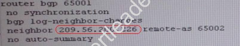
Since we are receiving icmp packets from Webserver interface on R1 so peering IP address under router BGP is configured wrong IP but with correct AS nos.
Change required: On R1 under router BGP Change neighbor 209.56.200.226 remote-as 65002 statement to neighbor 209.65.200.226 remote-as 65002
NEW QUESTION 10
Examine the output from R1. Interface FastEthernet0/0 is used for all management of the device. A client is able to connect to R1 on port 22, however, they are unable to connect on port 23. What is the cause of the problem?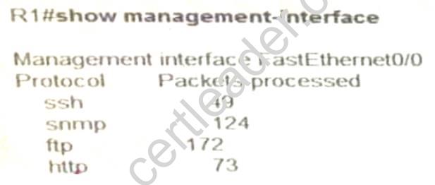
- A. Management Plane Protection (MPP) is enabled, however telnet is not allowed
- B. Telnet and SSH are not allowed at the same time.
- C. Management Plane Protection (MPP) is enabled, which only allows SSH
- D. Management Plane Protection (MPP) is enabled on the wrong interface
Answer: A
NEW QUESTION 11
Which command can you enter to block SSH traffic from hosts on network 10.10.15.0/24?
- A. access-list 142 deny tcp any 10.10.15.0 0.0.0.0 any eq 22
- B. access-list 142 deny tcp any 10.10.15.0 0.0.0.255 eq 21
- C. access-list 142 deny tcp 10.10.15.0 0.0.0.255 any eq 23
- D. access-list 142 deny tcp 10.10.15.0 0.0.0.255 any eq 22
Answer: D
NEW QUESTION 12
The implementations group has been using the test bed to do a ‘proof-of-concept’ that requires both Client 1 and Client 2 to access the WEB Server at 209.65.200.241. After several changes to the network
addressing, routing schemes, DHCP services, NTP services, layer 2 connectivity, FHRP services, and device security, a trouble ticket has been opened DSW1 will not become the active router for HSRP group 10.
Use the supported commands to isolated the cause of this fault and answer the following questions. The fault condition is related to which technology?
- A. NTP
- B. HSRP
- C. IP DHCP Helper
- D. IPv4 EIGRP Routing
- E. IPv6 RIP Routing
- F. IPv4 layer 3 security
- G. Switch-to-Switch Connectivity
- H. Loop Prevention
- I. Access Vlans
- J. Port Security
- K. VLAN ACL/Port ACL
- L. Switch Virtual Interface
Answer: B
Explanation: On DSW1, related to HSRP, under VLAN 10 change the given track 1 command to instead use the track 10 command.
Topic 18, Ticket 13: DHCP Issue
Topology Overview (Actual Troubleshooting lab design is for below network design)
Client Should have IP 10.2.1.3
EIGRP 100 is running between switch DSW1 & DSW2
OSPF (Process ID 1) is running between R1, R2, R3, R4
Network of OSPF is redistributed in EIGRP
BGP 65001 is configured on R1 with Webserver cloud AS 65002
HSRP is running between DSW1 & DSW2 Switches
The company has created the test bed shown in the layer 2 and layer 3 topology exhibits. This network consists of four routers, two layer 3 switches and two layer 2 switches.
In the IPv4 layer 3 topology, R1, R2, R3, and R4 are running OSPF with an OSPF process number 1. DSW1, DSW2 and R4 are running EIGRP with an AS of 10. Redistribution is enabled where necessary.
R1 is running a BGP AS with a number of 65001. This AS has an eBGP connection to AS 65002 in the ISP’s network. Because the company’s address space is in the private range.
R1 is also providing NAT translations between the inside (10.1.0.0/16 & 10.2.0.0/16) networks and outside (209.65.0.0/24) network.
ASW1 and ASW2 are layer 2 switches.
NTP is enabled on all devices with 209.65.200.226 serving as the master clock source.
The client workstations receive their IP address and default gateway via R4’s DHCP server.
The default gateway address of 10.2.1.254 is the IP address of HSRP group 10 which is running on DSW1 and DSW2.
In the IPv6 layer 3 topology R1, R2, and R3 are running OSPFv3 with an OSPF process number 6. DSW1, DSW2 and R4 are running RIPng process name RIP_ZONE.
The two IPv6 routing domains, OSPF 6 and RIPng are connected via GRE tunnel running over the underlying IPv4 OSPF domain. Redistrution is enabled where necessary.
Recently the implementation group has been using the test bed to do a ‘proof-of-concept’ on several implementations. This involved changing the configuration on one or more of the devices. You will be
presented with a series of trouble tickets related to issues introduced during these configurations.
Note: Although trouble tickets have many similar fault indications, each ticket has its own issue and solution.
Each ticket has 3 sub questions that need to be answered & topology remains same. Question-1 Fault is found on which device,
Question-2 Fault condition is related to,
Question-3 What exact problem is seen & what needs to be done for solution
===============================================================================
Solution
Steps need to follow as below:-
When we check on client 1 & Client 2 desktop we are not receiving DHCP address from R4 ipconfig ----- Client will be receiving Private IP address 169.254.X.X
From ASW1 we can ping 10.2.1.254….
On ASW1 VLAN10 is allowed in trunk & access command will is enabled on interface but DHCP IP address is not recd.
On R4 the DHCP IP address is not allowed for network 10.2.1.0/24 which clearly shows the problem lies on R4 & the problem is with DHCP
NEW QUESTION 13
Scenario:
You have been asked by your customer to help resolve issues in their routed network. Their network engineer has deployed HSRP. On closer inspection HSRP doesn't appear to be operating properly and it appears there are other network problems as well. You are to provide solutions to all the network problems.

Examine the configuration on R4. The routing table shows no entries for 172.16.10.0/24 and 172.16.20.0/24. Identify which of the following is the issue preventing route entries being installed on R4 routing table?
- A. HSRP issue between R4 and R2
- B. This is an OSPF issue between R4 and R2
- C. This is a DHCP issue between R4 and R2
- D. The distribute-list configured on R4 is blocking route entries
- E. The ACL configured on R4 is blocking inbound traffic on the interface connected to R2
Answer: D
Explanation: If we look at the configuration on R4 we see that there is a distribute list applied to OSPF, which blocks the 172.16.20.0/24 and 172.16.10.0/24 networks.
Topic 5, Troubleshooting OSPF
NEW QUESTION 14
You want to troubleshoot a GRE tunnel that is configured with an ACL. Which two tasks must you perform? (Choose two )
- A. Verify that the ACL permits TCP port 8080
- B. A Verify that the ACL permits IP protocol 47.
- C. Verity that the remote device is reachable across the network
- D. Verify that the IP addresses of the physical interfaces are on the same subnet
- E. Verify that the ACL permits TCP port 1723.
Answer: BC
Explanation: Topic 2, Troubleshooting VTP
NEW QUESTION 15
Which of the following are valid methods of providing a router with information concerning the location of the RP? (Choose all that apply.)
- A. Statically defined RP
- B. Bootstrap Router
- C. Auto-RP
- D. RP Discovery Protocol (RDP)
- E. RP Helios
- F. RPARP(RARP)
Answer: ABC
NEW QUESTION 16
The implementation group has been using the test bed to do an IPv6 'proof-of-concept1. After several changes to the network addressing and routing schemes, a trouble ticket has been opened indicating that the loopback address on R1 (2026::111:1) is not able to ping the loopback address on DSW2 (2026::102:1).
Use the supported commands to isolate the cause of this fault and answer the following question. On which device is the fault condition located?
- A. R1
- B. R2
- C. R3
- D. R4
- E. DSW1
- F. DSW2
- G. ASW1
- H. ASW2
Answer: C
Explanation: Start to troubleshoot this by pinging the loopback IPv6 address of DSW2 (2026::102:1). This can be pinged from DSW1, and R4, but not R3 or any other devices past that point. If we look at the routing table of R3, we see that there is no OSPF neighbor to R4:
Screen Shot 2015-03-11 at 4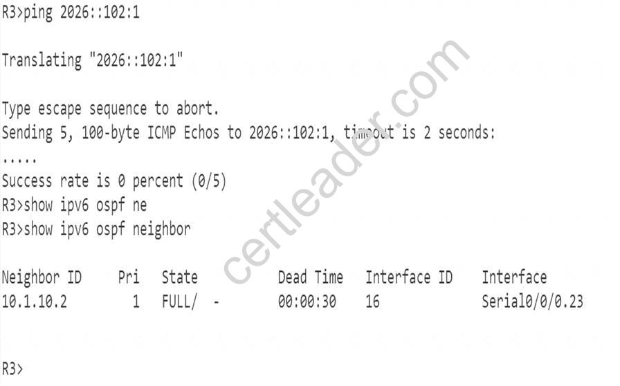
This is due to mismatched tunnel modes between R3 and R4: Screen Shot 2015-03-11 at 4
Problem is with R3, and to resolve the issue we should delete the “tunnel mode ipv6” under interface Tunnel 34.
NEW QUESTION 17
The implementation group has been using the test bed to do an IPv6 'proof-of-concept1. After several changes to the network addressing and routing schemes, a trouble ticket has been opened indicating that the loopback address on R1 (2026::111:1) is not able to ping the loopback address on DSW2 (2026::102:1).
Use the supported commands to isolate the cause of this fault and answer the following question.
On which device is the fault condition located?
- A. R1
- B. R2
- C. R3
- D. R4
- E. DSW1
- F. DSW2
- G. ASW1
- H. ASW2
Answer: B
Explanation: Start to troubleshoot this by pinging the loopback IPv6 address of DSW2 (2026::102:1). This can be pinged from DSW1, R4, and R3, which leads us to believe that the issue is with R2. Going further, we can see that R2 only has an IPV6 OSPF neighbor of R1, not R3:
Screen Shot 2015-03-11 at 10
We can then see that OSPFv3 has not been enabled on the interface to R3: Screen Shot 2015-03-11 at 10
So the problem is with R2, related to IPV6 Routing, and the fix is to enable the “ipv6 ospf 6 area 0”command under the serial 0/0/0.23 interface.
NEW QUESTION 18
The implementation group has been using the test bed to do an IPv6 'proof-of-concept1. After several changes to the network addressing and routing schemes, a trouble ticket has been opened indicating that the loopback address on R1 (2026::111:1) is not able to ping the loopback address on DSW2 (2026::102:1).
The fault condition is related to which technology?
- A. NTP
- B. IP DHCP Server
- C. IPv4 OSPF Routing
- D. IPv4 EIGRP Routing
- E. IPv4 Route Redistribution
- F. IPv6 RIP Routing
- G. IPv6 OSPF Routing
- H. IPV4 and IPV6 Interoperability
- I. IPv4 layer 3 security
Answer: G
Explanation: As explained earlier, the problem is with route redistribution on R4 of not redistributing RIP routes into OSPF for IPV6.
Thanks for reading the newest 300-135 exam dumps! We recommend you to try the PREMIUM 2passeasy 300-135 dumps in VCE and PDF here: https://www.2passeasy.com/dumps/300-135/ (156 Q&As Dumps)